Jeep Grand Cherokee Control Modules and Component Placement
An automated component placement line highlights the importance of correct parts, orientation and inspection before soldering.
Build quality starts with placement
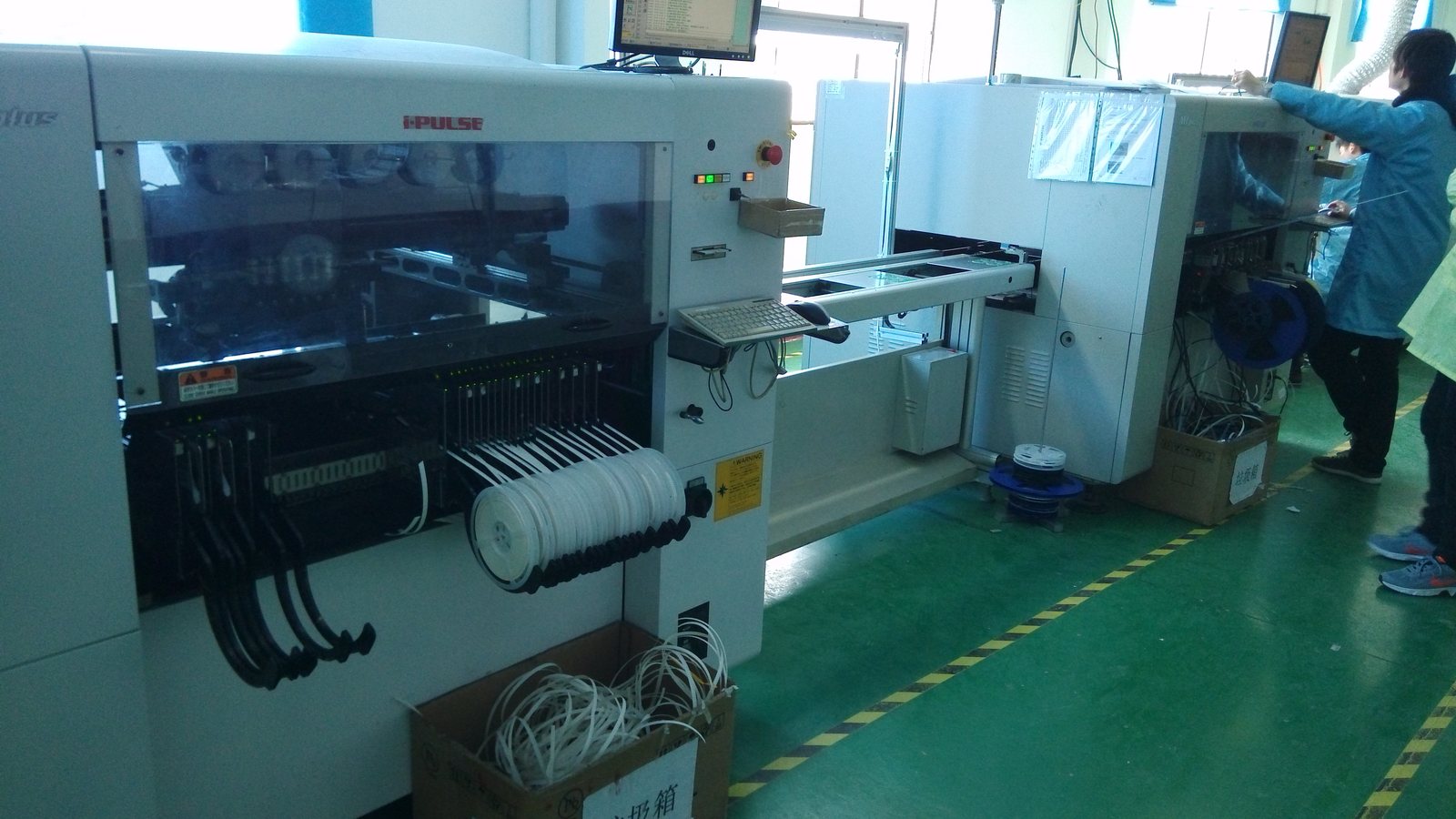
Component reels, feeder banks and enclosed assembly equipment define the scene in this photograph. Such production systems place electronic components onto circuit boards. For Jeep Grand Cherokee control module electronics, correct placement establishes the intended circuit before soldering. A misplaced component or incorrect orientation can affect operation even when the completed board looks orderly during a casual inspection.
Verify the feeder setup
The placement program must match the approved board revision and bill of materials. Check that each feeder contains the intended component and that replenishment preserves identification. Components with similar packages can have different electrical values. A useful process records reel information and verifies changes before production resumes. These controls help prevent an incorrect part from being repeated across an entire batch of boards.
Inspect orientation and position
Polarized components require the correct orientation relative to the board design. Optical inspection can examine location, rotation and visible assembly conditions against a reference program. Yamaha describes component mounters and automated optical inspection within its electronics production systems. Inspection results should identify the board and relevant component position. Investigating recurring offsets may reveal a feeder, nozzle, alignment or programming problem that needs correction.
Connect board assembly to module function
Placement checks form one stage of electronic quality assurance. Subsequent solder inspection and functional testing evaluate other characteristics of the finished assembly. Before discussing a Grand Cherokee replacement module, identify the exact hardware reference, software requirements and vehicle application. Installation may involve programming or configuration through the appropriate service procedure. For supplier evaluation, request evidence that links the module to its board revision and production records. A clear change history helps determine whether a later performance difference follows a component substitution, a manufacturing change or the configuration of the module itself. Include the reference photograph in the inspection record so that an operator can distinguish mirrored parts, reversed polarity markings and intentional empty positions on boards.