
Jeep Grand Cherokee Driveline Flanges and Hole Position
Circular flanged components beneath multiple spindles introduce the importance of hole location and a consistent machining datum.
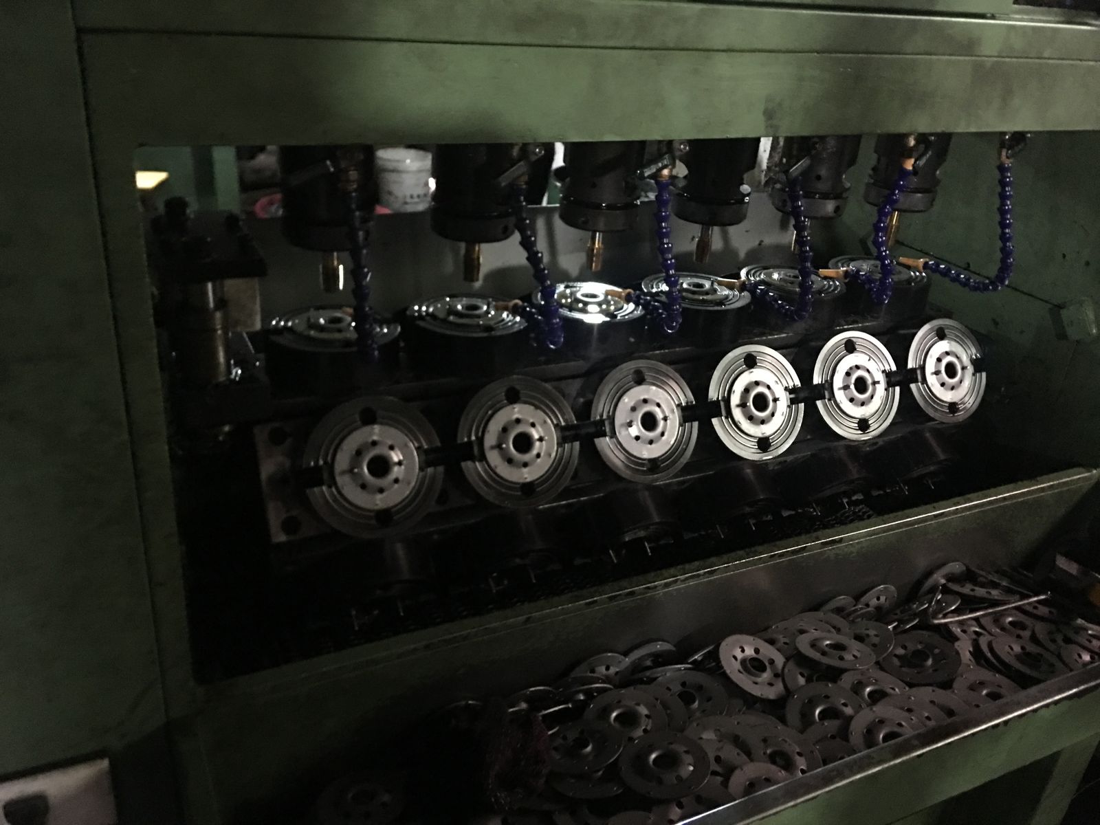
A mounting pattern has several dimensions
Rows of circular components beneath machining spindles make hole location the focus of this photograph. In Jeep Grand Cherokee driveline flange applications, a mounting pattern must work with its mating component. Hole diameter, spacing and position relative to the locating feature all matter. Evaluating only one hole size leaves important aspects of the assembly relationship unexamined.
Choose the correct datum
A machining datum establishes the reference from which dimensions are controlled. Depending on the design, a bore, face or other locating feature may be central to inspection. Ask which datum the drawing specifies and how the fixture reproduces it. Measure the relationship between locating and fastening features with appropriate equipment. A repeated offset can indicate a setup or locating issue even when individual hole diameters appear acceptable.
Examine the hole exits and mating face
Drilling can leave burrs at an exit or an intersecting feature. Inspect the relevant edges and remove burrs through a controlled operation that preserves the required shape. Check the mating face for raised material and trapped chips. Sandvik Coromant discusses how machining conditions influence hole quality. Use the drawing to distinguish permissible edge treatment from material removal that changes a functional dimension.
Confirm the assembled relationship
During a controlled fit check, the intended locating features should engage according to the design. Forcing fasteners into place can conceal an underlying alignment problem. A technician should verify the complete Grand Cherokee flange or shaft reference and follow the applicable assembly procedure. If a fit complaint occurs, record where the interference appears and measure both mating parts. Comparing the locating diameter, face condition and bolt pattern helps determine which relationship caused the problem. This approach gives purchasing teams a dimensional explanation they can discuss with the manufacturer. When the drawing calls for location tolerances relative to a reference bore, include that bore in the measurement setup and report the measured offset for each hole.